
see also: evolution propeller design methods
7-blade boat propeller: CFD vs BEM thrust B3-50 boat propeller: rpm for the required thrust Boat propeller: from Heliciel design to CFDHistory of the ship and boat propeller: technical developments from 1750 to 1907
The history of the boat propeller begins in 1752, when the Paris Academy of Sciences offers prizes to whoever brings significant progress to shipbuilding. Over a century and a half, inventors and engineers drew many of the ideas found on today's propellers: a shaft below the waterline, contra-rotating propellers, variable pitch and feathering, blade twist, flexible blades, air injection against cavitation. We go through them here in chronological order, from 1750 to the early twentieth century. The history of the propeller in general has already shown us the shape of the current propeller emerging gradually; here we look at the case of ships.
In this page:
- History of the boat propeller before 1836: Bernoulli, Bramah, Shorter
- Boat propeller from 1836 to 1860: contra-rotating, variable pitch, twist
- Boat propeller from 1871 to 1907: split blades, flexible blades and cavitation
- What became of these ideas?
This list is (very) quick and, of course, incomplete. It lets us see what our forebears did before we review the propeller propulsion systems currently used on boats.
1: History of the boat propeller before 1836: Bernoulli, Bramah, Shorter
In 1752 the Academy of Sciences of Paris offered a series of prizes to whoever made a significant contribution to shipbuilding. Bernoulli, Euler and d'Alembert looked into the problem. Bernoulli proposed a propeller, which won a prize and which looked like this:
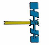
Bernoulli, 1752: a horizontal shaft carrying staged blades across the flow.
Thirty years later, in 1785, Bramah proposed a system with the propeller shaft below the waterline, as on our boats:
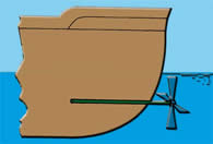
Bramah, 1785: the shaft goes through the stern below the waterline, the propeller is outside the hull.
In 1802 Shorter proposed a propeller that could drive sailboats in a dead calm. The propeller shaft stayed above the waterline, so no sealing was needed. This propeller was meant to be operated by men, using a capstan.
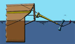
Shorter, 1802: the inclined shaft stays out of the water, only the propeller dips in.
2: Boat propeller from 1836 to 1860: contra-rotating, variable pitch, twist
In 1836 Ericsson drew a contra-rotating propeller: two propellers on the same axis, turning in opposite directions.
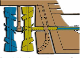
Ericsson, 1836: two propellers, one blue and one yellow, driven by concentric shafts.
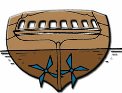
Taylor, 1838: two propellers placed on either side of the keel, seen from astern.
In 1849 Griffith drew a self-orienting, variable pitch propeller that could feather:
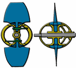
Griffith, 1849: on the left the propeller seen from the front, on the right from the side.
In 1851 Mangin tried to increase the thrust of the propeller by splitting the blade into two portions:
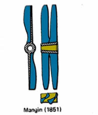
Mangin, 1851: the blade is doubled into two portions side by side.
In 1860 Hirsch filed a patent on a propeller with a twist distribution, but also a distribution of the radial positioning angle of the profiles:
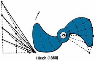
Hirsch, 1860: the twisted blade, with on the left the drawing of the angles of its sections.
3: Boat propeller from 1871 to 1907: split blades, flexible blades and cavitation
In 1871 Griffith took up Mangin's idea of splitting the blade in two, but over only part of the blade:
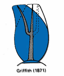
Griffith, 1871: the blade divides in two over only part of its length.
In 1886 Zeise continued developing the distribution of the pitch angle. He increased the pitch angle of the elements near the blade root, in order to increase the efficiency of that area of the propeller.
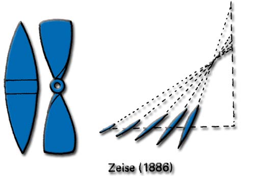
Zeise, 1886: on the right, the blade sections whose inclination increases towards the root.
In 1901 Zeise experimented with propellers with flexible blades:
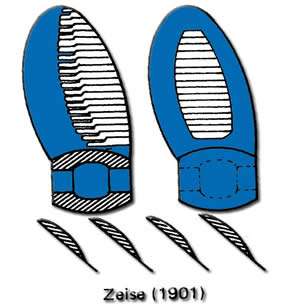
Zeise, 1901: hollowed blades with a flexible structure, with their profiles in cross-section.
In 1907 Taylor injected air onto the suction side of the propeller blade to reduce cavitation:
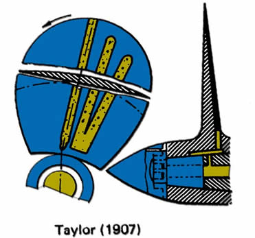
Taylor, 1907: channels carry air from the hub to the suction face of the blade.
4: What became of these ideas?
Countless other attempts and propeller experiments were of course made; we have only skimmed the evolution of boat propeller shapes. Several of these ideas have nevertheless stood the test of time. Griffith's propeller is the ancestor of variable pitch propellers and of folding or feathering propellers. Ericsson's contra-rotation is back in contra-rotating propeller projects. The pitch distribution of Hirsch and Zeise is the one described in the page on twist and pitch angle of the profiles. As for the air injected by Taylor, it tackles a problem that is as current as ever, cavitation.
Nowadays, the shape of propellers is still evolving, and the systems invented to increase their performance are numerous. This is proof, if any were needed, that the history of the propeller is far from over.
To go further, we can move from history to practice with the boat propeller design tutorial, or calculate the propeller that suits your boat with the propeller pitch calculator.
 Global site map
 Mecaflux
 Tutorials Mecaflux Pro3D
 Tutorials Heliciel
 Tutorials Heliciel PRO CFD
 Mecaflux Store
 Compare software functions
 Quotes, Orders, Payment Methods
 project technical studies